SLUICE GATES

Description

Suitable for manual operation provision may be made for power operation.Seasoned castings used for minimum distortion.Construction of ample weight and maximum rigidity. Robust sections of frame and door and scientific ribbing for additional strength.Adjustable wedge blocks to ensure positive closure of the shutter under low pressure or even back pressure conditions. Rising or non rising spindle of mild steel or stainless steel material.Foundation bolts for erecting the gate frame and operating hoist. A simple or worm geared operation hoist with gun metal nut and fitted with thrust ballbearing.Wall thimble to enable to remove the frame and shutter without disturbing concrete.

Design:

• Suitable for manual operation provision may be made for power operation

• Seasoned castings used for minimum distortion

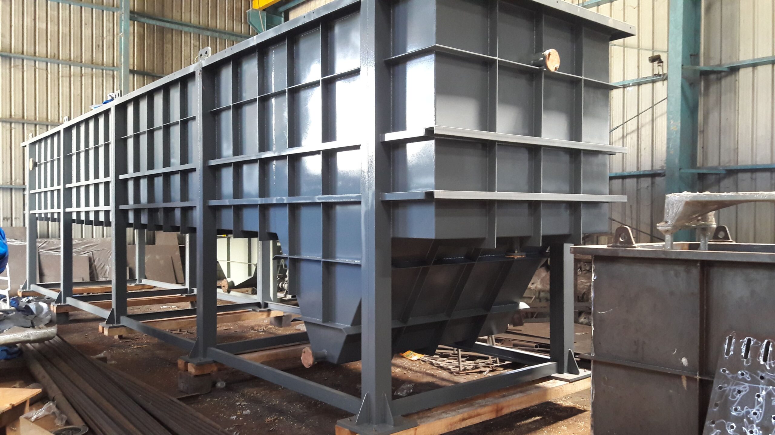
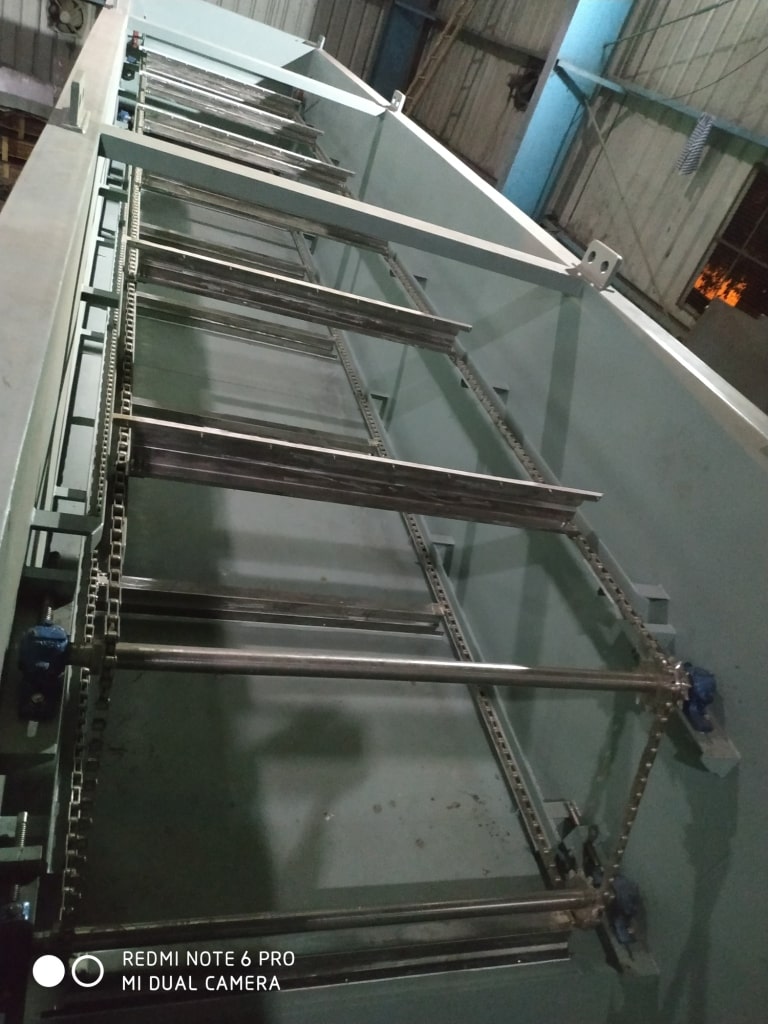
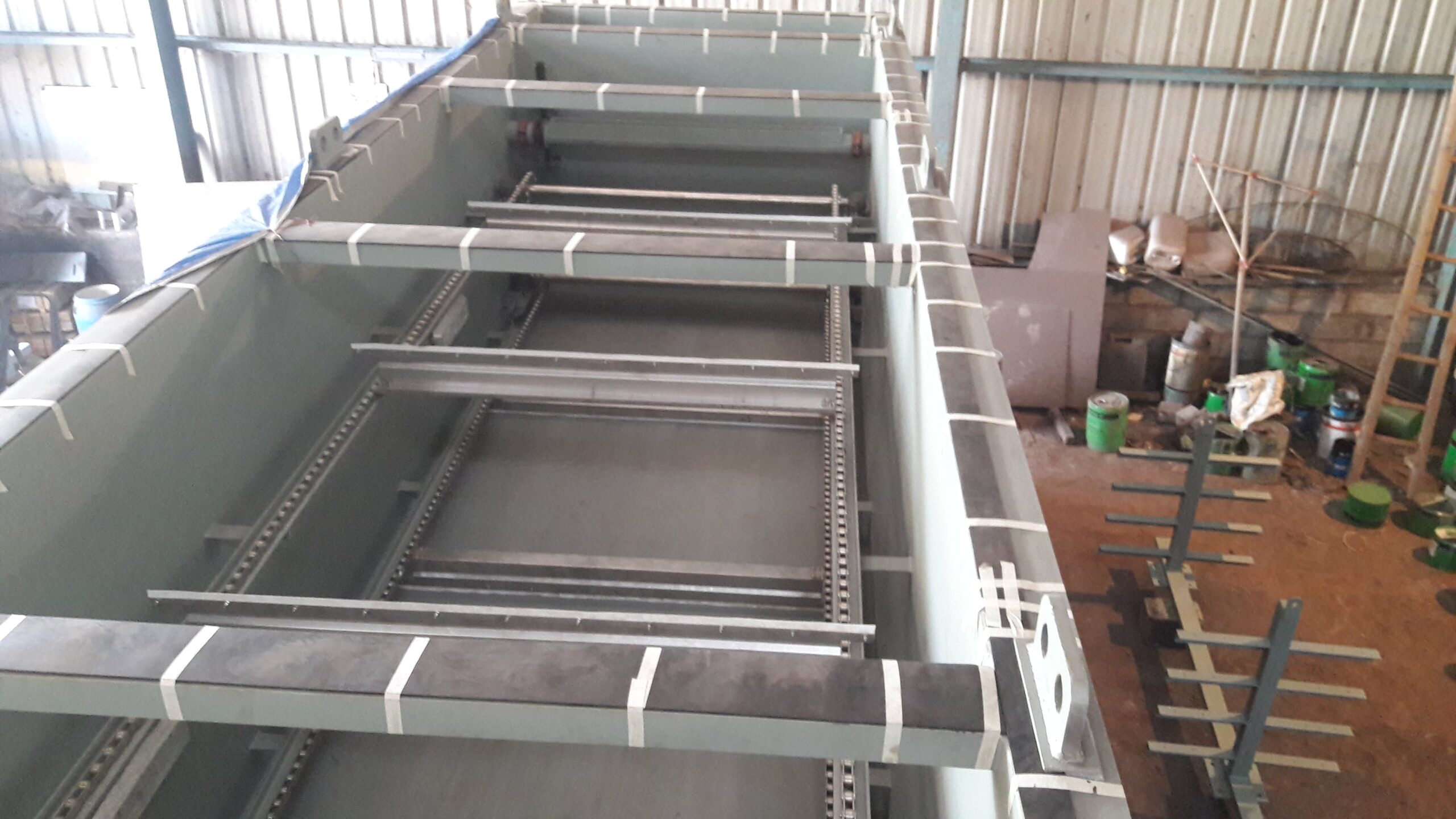
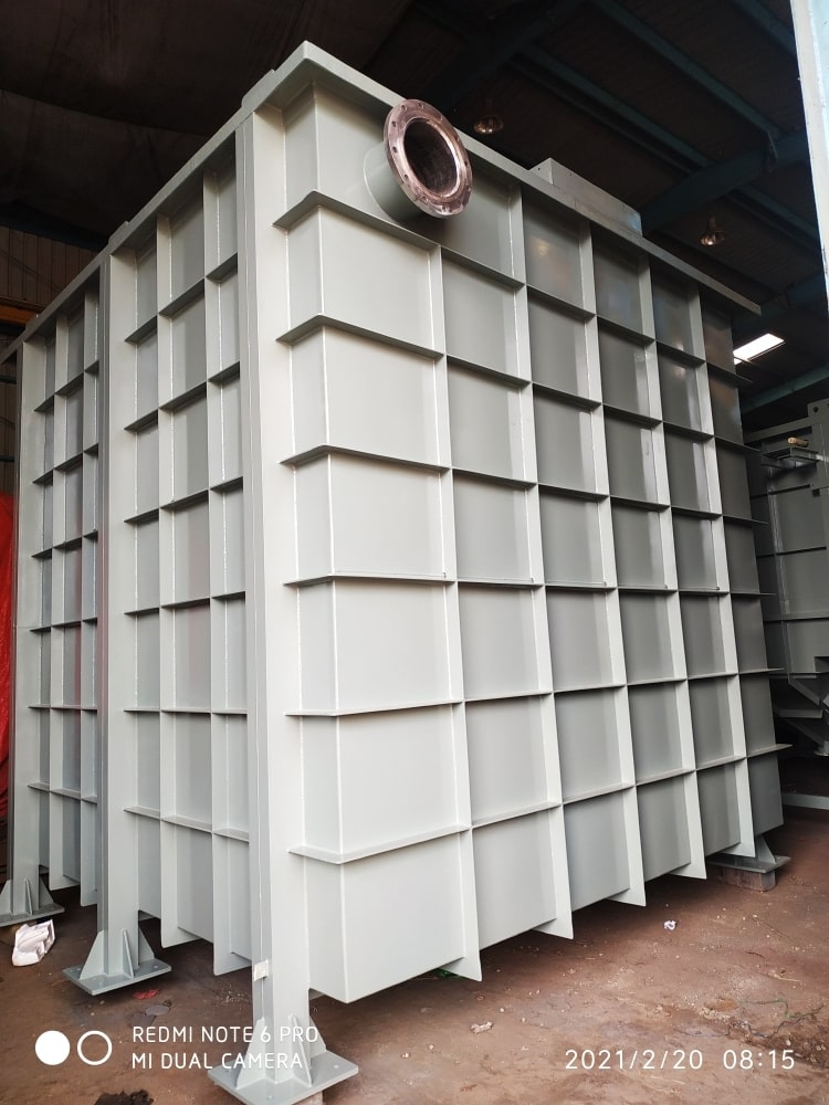
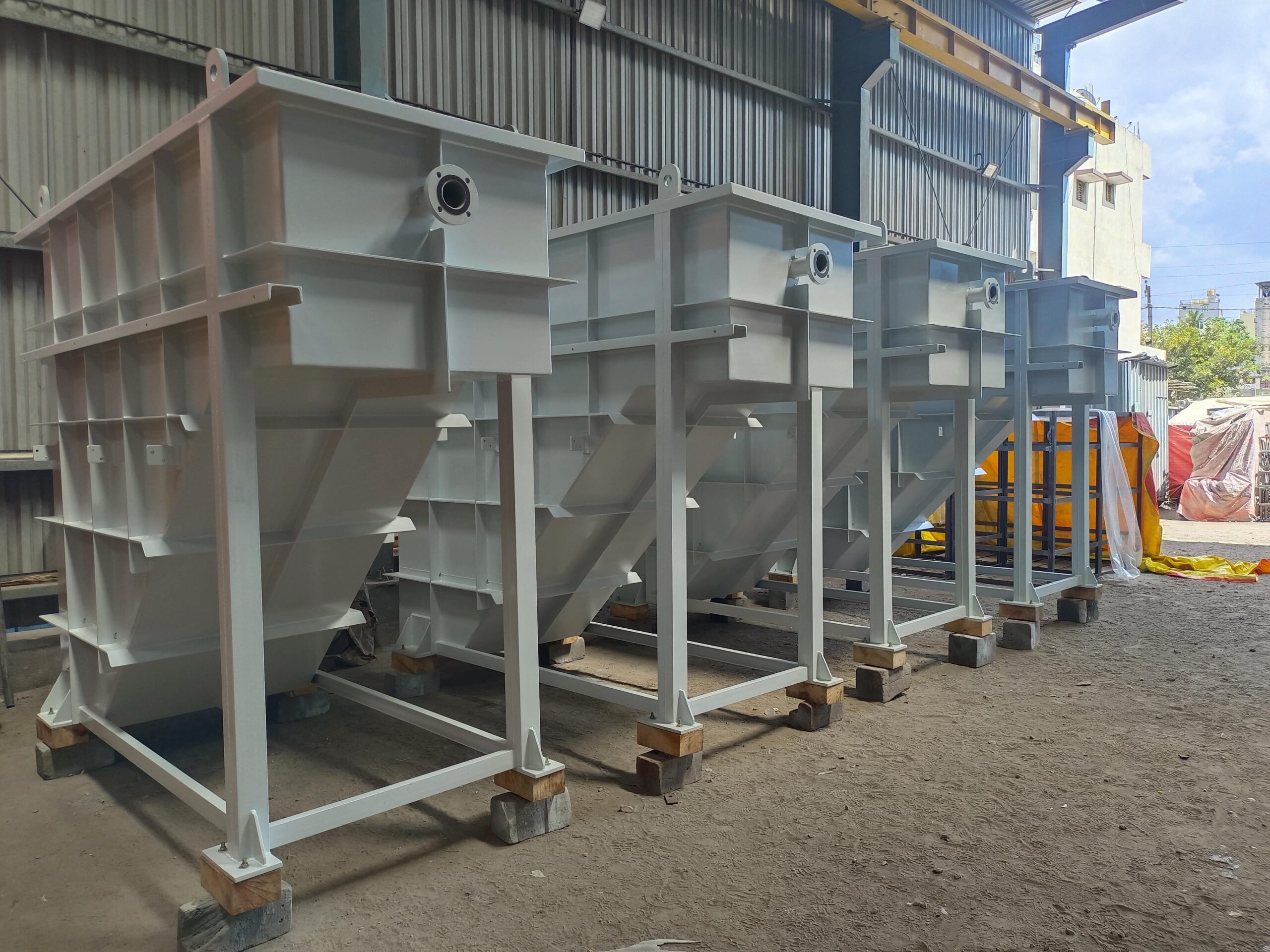
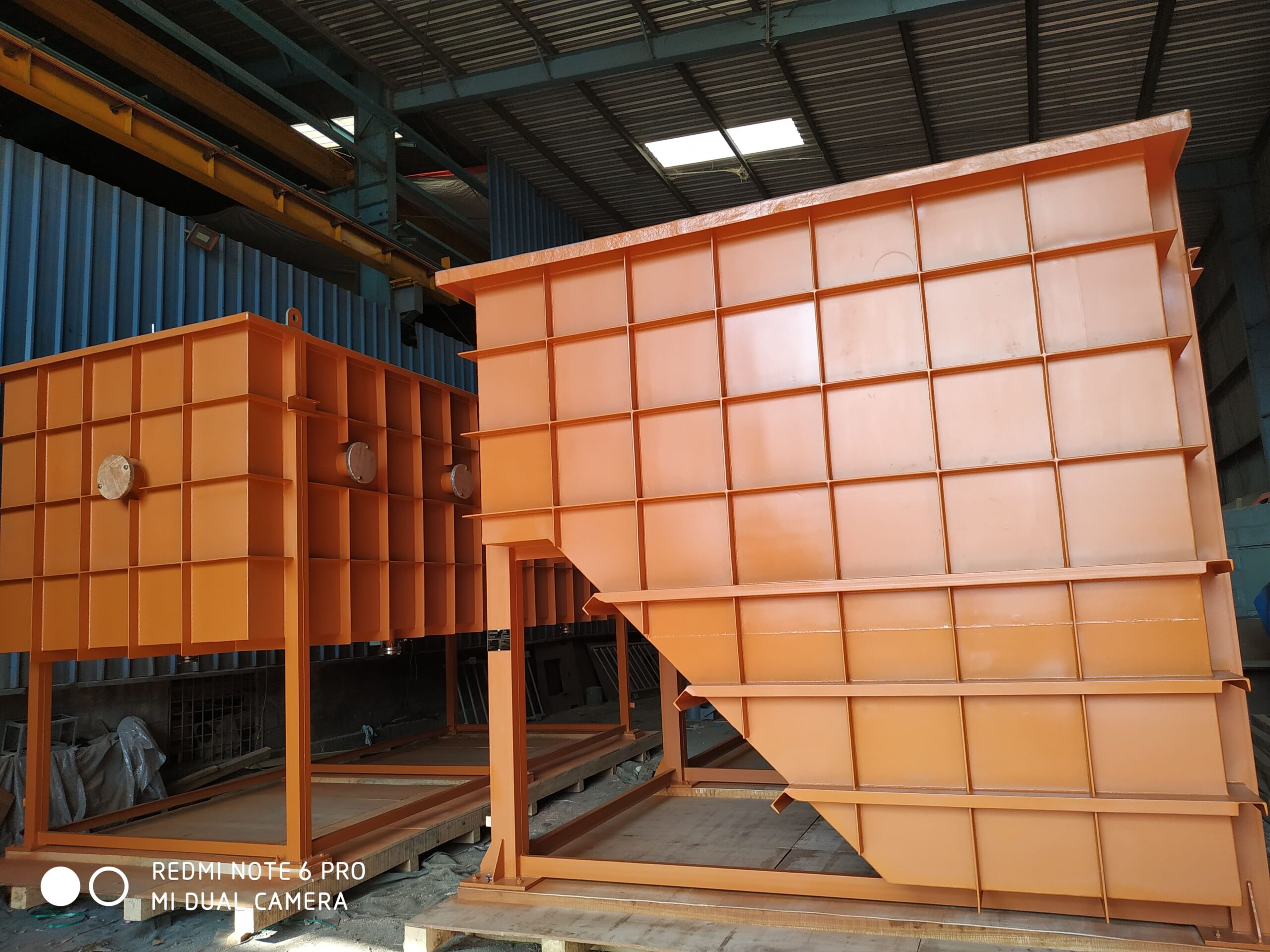
• Construction of ample weight and maximum rigidity. Robust sections of frame and door and scientific ribbing for additional strength

• Adjustable wedge blocks to ensure positive closure of the shutter under low pressure or even back pressure conditions

• Rising or non rising spindle of mild steel or stainless steel material

• Foundation bolts for erecting the gate frame and operating hoist. A simple or worm geared operation hoist with gun metal nut and fitted with thrust ballbearing

• Wall thimble to enable to remove the frame and shutter without disturbing concrete.

• Adjustale wall brackets having vertical and horizontal adjustments

• Flush bottom closing if desired in-lieu of the bottom seating face can be provided

Specifications:

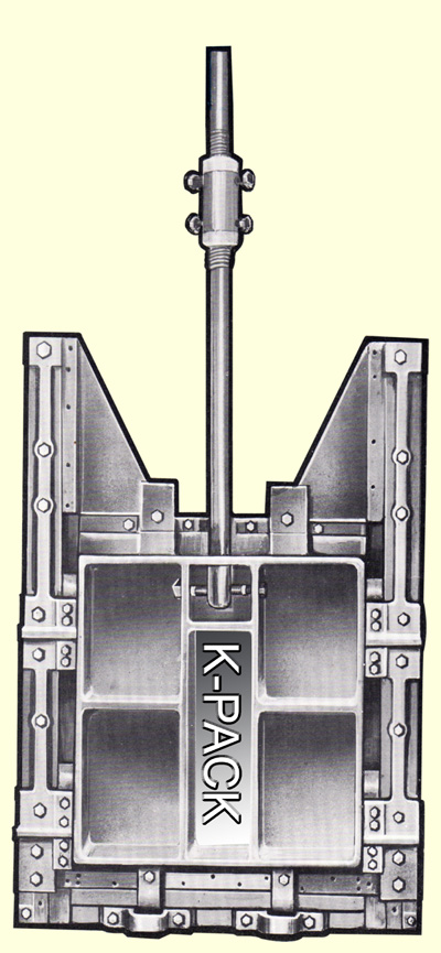
GATE FRAME: In closing grained homogeneous cast iron or mild steel fabricated with or without seating face secured by screws or rivets. Machined and hand scraped to match a similar face on door., Side guide strip of cast iron or mild steel with tapered wedges on the underside.

DOOR: of cast iron with cast reinforcements ribs or mild steel plate with vertical and horizontal stiffeners having seating face secured by screws or rivets, duly machined and hand scraped to match on then back tapered wedges to match tapered side guide strips on the frame

Integrally cast-lug to take a strong beating pin for non-rising spindle units on the integrally cast pocket to accommodate a Gun Metal nut.
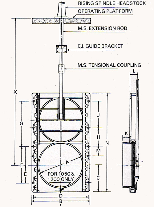
GA Drawings

Headstocks

The common arrangement for operating single-faced slice by hand operation. Depending on the nature of the spindle floor mounted headstocks are offered with extension rods, coupled and guide brackets.

• CAST IRON PILLAR

• HANDWHEEL

• GUN METAL NUT

• THRUST BALL BEARINGS

• BEARINGS GUN METAL BRUSHED ARE THE COMMON FEATURES

Other Products

API Separator

API
API1
API2

API separator is a generic term used to refer to the gravity-type rectangular channeled oil-water separator that is designed based on “API421 guidelines for design and operation of oil-water separators”. K-pack follows the first edition published in February 1990. This OWS [Oil-water separator] is designed for the separation of free-floating oil globules from the waste-water stream. The design is relayed on the density difference between oil globules to that of effluent water and is defined by ‘Stokes’s Law’ and is applied to the laminar flow condition.

Oil globule sizes of 150 microns and above are removed with closer to 90% design efficiency. When designed using API421 design criteria, the API channel leads to oil globule coalescing and rises due to buoyant forces to form an oil layer on top of the API channel. This layer is then scrapped off using a chain skimmer mechanism which also runs down to scrape off the heavier sludge which is collected at the bottom of the API separator. 

Applications:  The design is majorly used in refinery applications where a shock load of oil is expected which needs a larger area of separation. Also, the design is limited to the removal of free-floating oil of 150 microns and above only. 

Other Products

FLASH MIXER AND FLOCCULATOR

mixer
mixer1
mixer2

Flash mixers and Flocculators are conventional mixers used for chemical coagulation and flocculation in water and wastewater treatment processes.

The flash mixer is a rapid mixing unit that is designed for a retention time ranging from 30 seconds to 3 min [Typical]. The design of the Flash mixer includes impellor blades located connected vertical shaft and rotates in an axial direction.  This vertical shift is driven by a speed reducer [gear box] and an electrical motor.

Rapid mixing usually occurs in the regime of turbulent flow in which inertial flow predominates. Higher the velocity, and the greater the turbulence, the more efficient the mixing will be. The purpose of a Flash mixer is to destabilize or finely divide particles [impurities like solids or emulsified oil] using chemicals called coagulants. 

Typical chemicals used for chemical coagulation in water and wastewater industries are Alum [Aluminum Sulfate], FeCl3, and PAC [Poly Aluminum Chloride]. The chemical quantities that are to be added for the water and wastewater treatment process have to be found out through a jar test.

Flocculator is a slow mixing unit that is designed for a retention time ranging from 10 minutes to 30 minutes [Typical]. The flocculator design consists of a series of appropriately spaced paddles mounted on either horizontal or vertical shafts. This vertical shift is driven by a speed reducer [gear box] and an electrical motor.

The slow-moving paddles in the flocculator promote increased particle contact which in turn increases particle agglomeration or formation of flocs. Flocculation is a transport step that brings about the collisions between the destabilized particles [as a result of chemical coagulation] needed to form larger particles that can be removed readily by settling units [DAF or lamella]. 

Typical chemicals used for chemical flocculation in water and wastewater industries are Poly electrolytes [anionic or cationic]. The chemical quantities that are to be added for the water and wastewater treatment process have to be found out through a jar test.

Other Products

PIPE FLOCCULATOR

pipe
pipe1

A pipe flocculator is a plug-flow type reactor used for chemical coagulation, flocculation, de-emulsification, pH correction, etc under well-defined conditions. In a pipe flocculator, the mixing energy required for chemical mixing is obtained by turbulence in the main pipe and mixing pipe. The retention time is almost uniform and mixing energy is constant in the pipe cross-section. As such, all particles will be subjected to the same amount of mixing energy for the same period, which will result in a highly uniform chemical mixing with excellent separation characteristics.

A coagulant is usually dosed with raw water/effluent at the inlet of the pipe flocculator. Immediately after the dosing point a mixing unit is installed for the mixing where the coagulant mixes with effluent. Mixing energy and reaction energy in the mixing unit and the pipe is a result of turbulence (Reynolds number). 

Coagulation is the destabilization of the polluted matter in the raw water. Fine particles are formed, which are not ideal for separation. Flocculant has to be added to obtain separable particles. When the coagulation is completed a flocculant is dosed. The mixing of water and the flocculant takes place in a second mixing unit. Floc growth will further be completed in the pipe following the mixing unit. In this way a uniform, ideal floc can be formed for the separation of floc and water in a separator. 

Application: chemical coagulation, flocculation, de-emulsification, pH correction

Other Products

CPI/TPI Separator

TPI
TPI2

TPI [Tilted Plate Interceptor] separator also referred to as CPI [Corrugated Plate Interceptor] separator, parallel plate separator, or generally as the oil-water separator is designed based on “API421 guidelines for design and operation of oil-water separators”. TPI is designed for the separation of free-floating oil globules of 60 microns and above from the waste-water stream. The design is relayed on the density difference between oil globules to that of effluent water and is defined by ‘Stokes’s Law’ and is applied to the laminar flow condition.

TPI separator consists of parallel plates in the separation chamber resulting in the increased surface area due to the sum of horizontal projections of the corrugated plates added. 20 mm spacing is maintained between consecutive parallel plates between which the oil globules coalesce and rises along the inclined plates [usually inclined at 45 degrees] forming an oil layer on top of a process chamber. This top layer of oil is then skimmed off using a slotted pipe oil skimmer. Since the oil flow is counterflow to that of wastewater, the efficiency is at least 90%. The oil removal efficiency can be further increased up to 98% by adding a polypropylene [PP] coalescer mesh forming two stages of separation in a single TPI/CPI unit. The oil skimmer used in TPI can be a manually operated slotted pipe skimmer or a motorized slotted pipe oil skimmer, chosen based on the user’s requirements.

Since TSS [Total Suspended Solids] particle is co-flow to that of effluent flow, its reduction will be limited to 60-70% to that of inlet value.

Application: rainwater run-off treatment, tank storage farms, refinery, petroleum & petrochemical industry, oil rigs/produced water treatment, shipyard cleaning, train wash water, power plants., etc

Other Products